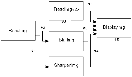
Figure B-1 Map Topology
This appendix describes the principles of module firing and describes how the firing algorithm works.
Module firing is controlled by the MCW through the firing algorithm. The task of the firing algorithm is to gather and organize data on each input port and send the data in an orderly fashion to the user function, then to retrieve it from the output port(s) and send it to the next module. Three types of events affect module firing in an IRIS Explorer map. They are:
Topology changes are caused by these events:
Data arrival includes:
Module firing may result from:
The map topology controls the propagation of frames of data. A frame is the unifying principle into which data arriving on a module port is fitted. Because the firing algorithm is distributed among modules, each module needs to know some part of the map topology in order to decide when to execute.
Each module stores a topology influence table that lists, for each connection, which upstream modules the connection depends on for data. If we think of each connection as storing a bit-vector corresponding to all modules, then that connection marks bits true for each upstream module. The list of modules includes the UI control panel that sends widget values to the module. For example, the map in Figure B-1 generates the dependency table for DisplayImg shown in Table B-1.
| Source | |||||
|---|---|---|---|---|---|
| Connection # | ReadImg<2> | ReadImg | BlurImg | SharpenImg | DisplayImg (UI) |
| 1 | n | ||||
| 2 | n | ||||
| 3 | n | n | |||
| 4 | n | n | |||
| 5 | n |
The connection numbers in the table relate to the numbered wires in the map.

The module employs the table by ANDing the frame ID bit-vector against each connection bit-vector to see whether data should be expected on that connection. This allows the multi-module frame IDs that are needed by the UI for vector widget settings.
When map topology changes, modules must be informed of the new topology so that they can correctly update their topology influence tables. No further action is required when topology changes do not coincide with propagation of data frames. However, when there are partial frames in existence, special action is needed to handle them.
On deletion of a connection, all frames waiting for data on that connection can mark that data as arrived (but old). This prevents frames from waiting indefinitely for data that will never arrive. It is especially important when disconnections occur due to module death, because there is no possibility of the upstream module fixing up the frame.
When a new connection is made, the ensuing data that arrives on the connection is marked as special. That data goes into a separate frame and is sent to the input ports. This is so that input connection data updates the module as soon as possible.
The assembly of multiple independent frames of input data within a module is one of the major innovations of this firing algorithm. The diamond map illustrates the basic concept of the firing algorithm. Under normal circumstance, when we fire module A, for instance through a widget manipulation, we expect B and C both to fire, and D to fire only once. The firing of D waits for the two inputs descended from A (from modules B and C). This firing behavior has these advantages:
Figure B-2 shows the possibility for confusion when a map is fired and several datasets move downstream. There are four modules, A, B, C, and D, and six connections that we are interested in. Module A is wired to modules B and C and modules B and C both have two connections to module D. Each dataset flowing through the map carries with it information about the module that initiated it. Each module contains a topology influence table that allows it to compute the set of ports to invalidate in the event that another port receives data from a given upstream module. In this case, D's table says that both ports depend on data from module A, so that arrival of data from module A on port 1 (via module B) should also invalidate port 2 (from C).
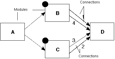
This version of the diamond map shows two firings, one each of modules B and C. Now B and C each have two data connections to module D. Because B and C are fired almost simultaneously, we could end up with a race condition between dataset arrival in module D. The arrival ordering is numbered on the respective connections. The correct firing behavior of D is to fire twice, once with the outputs of B and once with the outputs of C. It would be wrong to fire only once with all four datasets, which we call frame mixing.
The correct order of firing on D in this example is with datasets (2,3) first because this is the first frame to be completed. This speeds execution of the map. D's inputs on the first firing are 1-previous, 2-current, 3-current, 4-previous. On the second firing, they are 1-current, 2-current, 3-current, 4-current. It does not swap out datasets 2 and 3 when firing on datasets 1 and 4.
To summarize:
To avoiding data loss, we require multiple independent frames created in D to include the possibility of several frames from the same originator. And in order to correctly associate data with its frame, each dataset in the map, and each frame being collected in a module must carry a frame identifier which must:
The set of frame identifiers forms a partially-ordered space. Frames with different originators are unordered, while frames from a single originator are ordered by their sequence order of creation.
The information carried in the frame includes:
The originator ID and sequence number uniquely identify a frame. The extra predecessor information is used to add dependency on a previous frame in the case of multiple output data flushes caused by arrival of an upstream frame. This helps to maintain the partial ordering of frames in downstream modules.
Because data cannot leapfrog through the map, we can be sure that two frames of data from a single originator will arrive in the same order at all downstream modules in the map. The non-leapfrogging of data in a map need not imply that those datasets are in ordered frames, however.
Figure B-3 illustrates how frame identifiers can keep data ordered when there is a multiple data flush. When a module fires due to an upstream event, it copies the frame identifier from its input frame over to its output frame. This allows it to propagate the correct frame identifier through the downstream portion of the map. But when a module sends several sets of output by using the cxOutputDataFlush routine (three shaded circles on B.*), assigning that upstream frame identifier to all of its output frames would force the downstream map of out sync, creating a deadlock (module C.1 would expect multiple inputs from A.1 on its first port). Thus the second and all subsequent flushes must create a new frame identifier listing the flushing module as the originator.
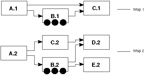
B.*'s frames must be ordered with respect to A.*'s frames. Merely following them in the map along the path to C.1 is not enough, for there could be a race condition if there were other paths to C.1. For instance, in the second map in Figure B-3, if C.2 takes a long time to arrive, then multiple complete frames from B.2 may arrive at D.2 before the A.2 frame is completed at D.2.
The B.2 frame is dependent on an A.2 frame because each frame carries dependency information, some implicit, some explicit. The explicit information is of the form "B.2(1) depends on A.2" for the examples above. The implicit information is that X(n) depends on X(m) if m < n, the usual execution ordering. A single predecessor is sufficient, because of transitivity of dependencies.
If D.2 fires when it gets a complete frame from B.2, without waiting for the A.2 frame, D.2 could end up with inconsistent data, some from the A.2 and B.2 frames (through B.2) and some from before the A.2 frame (through previous data from C.2).
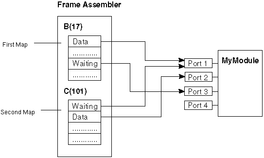
Figure B-4 shows a map with two firings. Modules B and C have each output data from two ports, and MyModule has received the data on three of its ports.
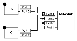
Figure B-5 shows a snapshot of the firing process. It illustrates the frame assembler after it has received Port 1 data from B and Port 2 data from C. Each frame has a slot for each port, with these three possible states:
When all "waiting" slots are filled, and if this frame has no dependencies on incomplete frames, the datasets are sent to the ports of the module. No datasets are sent until the frame fills.
The data structure used to represent the incomplete frames in a module is known as a "forest of trees". Each independent tree represents an independent firing upstream of the module. All frames within a single tree represent dependent frames, typically the result of repeated module flushes. Any complete frame at the root of a tree can be sent to the module's input ports.
The dependency arcs in the frame graph are constructed from the predecessor information and from the previous frame table. This table lists, for each upstream module, the latest frame originated by that module that is still pending in the frame graph. When a new frame arrives from that same module, the previous frame information is used to create a dependency arc and the table is updated.
The actual computation is: when data arrives on a link, for each module in the union of Frame ID and topology influence table, make this frame depend on previous frame from that module. When the last partial frame from an upstream module is filled and enqueued for processing by the ports, the relevant entry in the previous frame table is emptied, for there are now no partial frame dependencies on that upstream module.
You can store all dependency arcs in the upstream partial frame, which simplifies scheduling of frames. When data arrives on a frame with no dependencies, that frame is enqueued. When the frame is processed by the ports, all partial frames that depend on it have their dependency counts decremented. This has two advantages: it does the correct breadth-first scheduling of completed frames, and it uses the ports queue to help out, rather than implementing a second queue for scheduling. As a result, each frame also has a dependency count of the number of previous partial frames it depends on.
Several API routines let you send multiple ports at once during a simulation. These include:
The purpose of cxOutputDataSendNow is to support asynchronous parallel execution of downstream sub-maps, by sending data as soon as they are ready, rather than erecting a wait barrier on completion of the entire output frame.
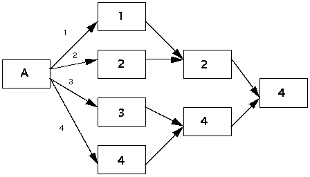
For instance, the map in Figure B-6 shows how many downstream modules can fire before the reader has sent output on all ports. The independent flows of data are labelled 1, 2, 3, and 4 on the output arcs. Modules are labelled with corresponding numbers to show which dataset sending causes them to fire. One module can fire when the first dataset is emitted from A, two on the second dataset, one on the third, and three on the fourth.
To handle fan-in of input data, data are gathered per connection, rather than per port. This allows multiple datasets to be gathered into a single frame with no loss of data and no additional firings.
The frame is not considered complete until all of its connections, be they single or fanned in, present data from the upstream frame. An entire, completed frame of data is them delivered to the module's ports simultaneously. This means that a fan-in port will receive multiple datasets together.
You have access to these datasets through cxInputDataGetV, which returns a pointer to a static vector of dataset pointers.
cxInputDataGet returns a single dataset pointer even when the port contains a vector of datasets. The routine returns the new dataset from the most recently wired connection or, if there is no new dataset, the previously returned dataset.
cxInputDataChangedV returns a static Boolean (int) vector of dataset state.
The routines cxInputDataConnIDGet and cxInputDataConnIDGetV return the connection identifier(s) for a given port, in wiring order. You are referred to the IRIS Explorer Reference Pages for a full description of their functionality.
Note: Only one dataset can flow on a single wire at a given time.
When a new frame of data has been filled and finally made it through the frame queue, it arrives at the input port, where its datasets are merged with the previous port data by overlaying new data. Old data on a link with new data are replaced, while all links not carrying new data in the frame are marked as old on the port. The link with the newest data, either the most recently wired link with new data, or the most recently wired with old data, becomes the focus for the single dataset API. If the newest link is deleted in the arriving frame, then that frame's newest link takes on that role.
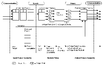
This sequence of events is shown in Figure B-7.
After the data are merged into the ports, each new dataset is checked for constraint correctness. If a dataset fails, it is released from the port's link (making that link empty), a modAlert is issued, and the user function is not fired.
The user function might be legally fireable, for instance if the port with bad data were optional, so that an empty port would be acceptable. However, since the new dataset on this frame was not legal, firing the module in the absence of that dataset would not give the correct or expected results. If multiple datasets are in error, they can be flagged and rejected all together.
A fan-in port with five links and only four datasets (i.e., one link is empty) will not fire if the port is marked Required. Thus a port's links must each meet the Required test for data before the port is considered satisfied.
A disabled module handles new frames by merging them onto the input ports, then sending a NULL (synchronization) frame downstream; the user function is not called. When the module is enabled, if there is an unused partial frame merged into the input ports, then the user function is called.
Parameters both with widgets and without widgets now live in modules. They all obey the firing algorithm, which eliminates unwanted multiple firings. This leaves the GUI to perform two parameter-related actions:
Parameter functions (P-Funcs) are dealt with in the same way: their ownership is pushed down to the module.
In order to change several widget values simultaneously, there must be a single firing frame for the multiple widget values. You can thus make several changes to disabled modules, then re-enable the modules together, and the resulting parameters are sent as a vector of widget settings. This is the widget analogue of a frame of data comprising outputs on multiple ports.
The event that causes a vector of widget settings is the enabling of a module or modules. This can be done with the Enable menu item on a module control panel, with the Enable All menu item in the Map Editor, or by launching a module or map. In each case, the subsequent set of module enables is considered to be a single, atomic event.
This event is tagged by including the UI module identifiers of all relevant modules in the frame of data propagated from the UI modules into the map. Thus instead of having a single initiator, the frame has several UI module initiators. The fact that we can represent them all in a single frame means that we can synchronize the firing due to the multiple enables.
There are four times when a widget value must be set:
However, only the latter three require a message from the module to the GUI, since the GUI creates the new parameter value in the first case. When a new parameter arrives from an upstream module, the widget is not set until the input data frame is delivered to the input ports.
When there are both widgets and Pfuncs on a fan-in port, the user sees either the fan-in connections or the Pfuncs, but not both.